Tag Archives: vsanDatastore

Cache Sizing

Since vSAN was released in 2014 there has been a bit of confusion as to how much cache should be sized for the cluster, this article is intended to clear that up and provide direction for both Hybrid and All-Flash configurations.? The reason there are differences in the recommendations is primarily because in Hybrid the cache is a Read Cache as well as a Write Buffer and in All-Flash it’s just serving as a Write Buffer, so the sizing is not a “one size fits all”.

Capacity Definitions:

  • RAW Capacity – This is the amount of capacity the vSAN Datastore will provide
  • Usable Capacity – This is the amount of capacity that can be provided based on the FTT level specified in storage policies
  • Provisioned / Deployed Capacity – This is the amount of space taken by objects before FTT is taken into account
  • Consumed Capacity – This is the amount of space that has been consumed by objects taking into account FTT, for example a 100GB Object with FTT=1 will consume 200GB of storage space


Hybrid Cache Sizing
In Hybrid the recommendation has always been 10% of Usable Capacity or Deployed capacity, if we have a 3-Node vSAN cluster, each host has two disk groups and each disk group has 7×1.2TB 10K SAS Drives, that means each host has 16.8TB of RAW Capacity and our 3-Node cluster has 50.4TB of RAW Capacity, based on the following FTT Values in our storage policy this means our total Usable Capacity is:

FTT=0 – 50.4TB
FTT=1 – 25.2TB
FTT=2 – 16.8TB
FTT=3 – 12.6TB

Based on the 10% rule our cache requirements are as follows:

FTT=0 – 5.4TB which equates to 1.8TB Per node which equates to 900GB Per Disk Group
FTT=1 – 2.52TB which equates to 0.84TB Per node which equates to 420GB Per Disk Group
FTT=2 – 1.68TB which equates to 0.56TB Per node which equates to 280GB Per Disk Group
FTT=3 – 1.26TB which equates to 0.42TB Per node which equates to 210GB Per Disk Group

The above sizing is all well and good if you are only using a single FTT method, however vSAN allows you to define policies with different FTT levels which means you can have objects on vSAN that have varying levels of protection, this makes sizing using the above method all the more difficult.

The best way to size the cache in a Hybrid cluster is to base it on your deployed or provisioned capacity, for example in the above RAW capacity of 50.4TB you may choose to have the following as an example

10 Objects based on FTT=0 of 500GB which totals 5TB of Provisioned Capacity and 5TB of Consumed Capacity
10 Objects based on FTT=1 of 500GB which totals 5TB of Provisioned Capacity and 10TB of Consumed Capacty
10 Objects based on FTT=2 of 500GB which totals 5TB of Provisioned Capacity and 15TB of Consumed Capacity
10 Objects based on FTT=3 of 500GB which totals 5TB of Provisioned Capacity and 20TB of Consumed Capacity

If you total up the above, our Provisioned Capacity is 20TB but our Consumed Capacity is 50TB, based on the Provisioned Capacity of 20TB, 10% of this is 2TB which equates to 0.67TB Per Node, or 333GB per Disk Group, this is how your cache in Hybrid should be sized.

All-Flash Cache Sizing
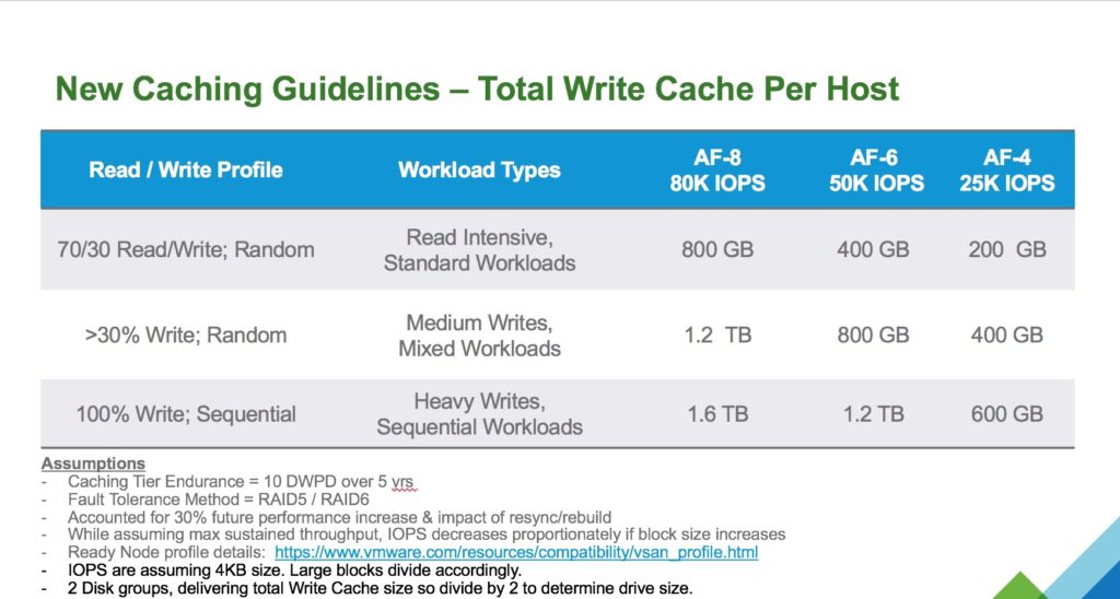
All flash has a lot more factors to consider, Erasure Coding, Dedupe and Compression and the fact that the cache is purely a Write Buffer so we have to take into account write endurance so the usual 10% sizing does not apply here.? In reality the typical 70% Read / 30% Write workload means that a lot of the requests are coming from the Capacity Tier which in this case is flash based anyway, so this means that the cache layer can be much smaller than it would have been in Hybrid for the same RAW capacity, however there is the write endurance factor to take into account.? We all know there is a write buffer limit in vSAN but that does not mean you should limit the size of the SSD drives based on that, the main reason is to increase the endurance of the drive, vSAN will cycle through all the cells on the drive irrelevant of the Write Buffer Limit.? VMware recently published a new sizing guide for All-Flash which is shown below


There we have it!


Creating a vSAN Cluster without a vCenter Server

I have been asked many times about creating a 3-node vSAN cluster without a vCenter server, the main reason for doing this is that you need to place your vCenter server onto the vSAN datastore but have no where to host the vCenter server until doing so.? The many customers I have spoken to are not aware that they can do this from the command line very easily.? In order to do this you must have installed ESXi 6.0 U2 and enabled SSH access to the host, there are a few steps in order to do this

  1. Configure the vSAN VMKernel Interface
  2. Create the vSAN Cluster
  3. Add the other nodes to the cluster
  4. Claim the disks

Step 1 – Create the VMKernel interface
In order for vSAN to function you need to create a VMKernel Interface on each host, this requires other dependencies such as a vSwitch and a Port Group, so performing this on all three hosts is a must so lets do it in this order, firstly lets create our vSwitch, since vSwitch0 exists for the management network we’ll create a vSwitch1

esxcli network vswitch standard add -v vSwitch1

Once our vSwitch1 is created we then need to add the physical uplinks to our switch, to help identify which uplinks to use we run the following command

esxcli network nic list

This should return details on all the physical network cards on the host for example:

Name PCI Driver Link Speed Duplex MAC Address MTU Description
vmnic0 0000:01:00.0 ntg3 Up 1000Mbps Full 44:a8:42:29:fe:98 1500 Broadcom Corporation NetXtreme BCM5720 Gigabit Ethernet
vmnic1 0000:01:00.1 ntg3 Up 1000Mbps Full 44:a8:42:29:fe:99 1500 Broadcom Corporation NetXtreme BCM5720 Gigabit Ethernet
vmnic2 0000:02:00.0 ntg3 Down 0Mbps Half 44:a8:42:29:fe:9a 1500 Broadcom Corporation NetXtreme BCM5720 Gigabit Ethernet
vmnic3 0000:02:00.1 ntg3 Down 0Mbps Half 44:a8:42:29:fe:9b 1500 Broadcom Corporation NetXtreme BCM5720 Gigabit Ethernet
vmnic4 0000:82:00.0 ixgbe Up 10000Mbps Full a0:36:9f:78:94:cc 1500 Intel Corporation Ethernet Controller 10 Gigabit X540-AT2
vmnic5 0000:82:00.1 ixgbe Up 10000Mbps Full a0:36:9f:78:94:ce 1500?? Intel Corporation Ethernet Controller 10 Gigabit X540-AT2
vmnic6 0000:04:00.0 ixgbe Up 10000Mbps Full a0:36:9f:78:94:c4 1500 Intel Corporation Ethernet Controller 10 Gigabit X540-AT2
vmnic7 0000:04:00.1 ixgbe Up 10000Mbps Full a0:36:9f:78:94:c6 1500 Intel Corporation Ethernet Controller 10 Gigabit X540-AT2

For my cluster I am going to add vmnic5 to the vSwitch1 so for this I run the following command:

esxcli network vswitch standard uplink add -v vSwitch1 -u vmnic5

Now that we now have our uplink connected to vSwitch1 we need to configure a portGroup for vSAN, for this I am calling my portGroup name “vSAN”

esxcfg-vswitch -A vSAN vSwitch1

Now we need to create out VMKernel interface with an IP Address (192.168.100.1 for Host 1), Subnet Mask and assign it to the “vSAN” portGroup

esxcfg-vmknic -a -i 192.168.100.1 -n 255.255.255.0 -p vSAN

We validate our VMKernel Interface by running the following command:

[root@se-emea-vsan01:~] esxcfg-vmknic -l
Interface Port Group/DVPort/Opaque Network IP Family IP Address Netmask Broadcast MAC Address MTU TSO MSS Enabled Type NetStack
vmk0 Management Network IPv4 172.16.101.1 255.255.252.0 172.16.103.255 44:a8:42:29:fe:98 1500 65535 true STATIC defaultTcpipStack
vmk1 vSAN IPv4 192.168.100.1 255.255.255.0 192.168.100.255 00:50:56:6a:5d:06 1500 65535 true STATIC defaultTcpipStack

In order to add the VMKernel interface to vSAN we need to run the following command:

esxcli vsan network ip add -i vmk1

Repeat the above steps on the two remaining hosts that you wish to participate in the cluster

Step 2 – Creating the cluster
Once we have all the VMKernel interfaces configured on all hosts, we now need to create a vSAN Cluster on the first host, to do this we run the following command

esxcli vsan cluster new

Once completed we can get our vSAN Cluster UUID by running the following command:

[root@se-emea-vsan01:~] esxcli vsan cluster get
Cluster Information
 Enabled: true
 Current Local Time: 2016-11-21T15:17:57Z
 Local Node UUID: 582a29ea-cbfc-195e-f794-a0369f7894c4
 Local Node Type: NORMAL
 Local Node State: MASTER
 Local Node Health State: HEALTHY
 Sub-Cluster Master UUID: 582a2bba-0fd8-b45a-7460-a0369f749a0c
 Sub-Cluster Backup UUID: 582a29ea-cbfc-195e-f794-a0369f7894c4
 Sub-Cluster UUID: 52bca225-0520-fd68-46c4-5e7edca5dfbd
 Sub-Cluster Membership Entry Revision: 6
 Sub-Cluster Member Count: 1
 Sub-Cluster Member UUIDs: 582a29ea-cbfc-195e-f794-a0369f7894c4
 Sub-Cluster Membership UUID: d2dd2c58-da70-bbb9-9e1a-a0369f749a0c

Step 3 – Adding the other nodes to the cluster
From the remaining hosts run the following command adding them to the newly created cluster

esxcli vsan cluster join -u 52bca225-0520-fd68-46c4-5e7edca5dfbd

You can verify that the nodes have successfully joined the cluster by running the same command we ran earlier noting that the Sub-Cluster Member Count has increased to 3 and it also shows the other sub cluster UUID Members:

[root@se-emea-vsan01:~] esxcli vsan cluster get
Cluster Information
 Enabled: true
 Current Local Time: 2016-11-21T15:17:57Z
 Local Node UUID: 582a29ea-cbfc-195e-f794-a0369f7894c4
 Local Node Type: NORMAL
 Local Node State: MASTER
 Local Node Health State: HEALTHY
 Sub-Cluster Master UUID: 582a2bba-0fd8-b45a-7460-a0369f749a0c
 Sub-Cluster Backup UUID: 582a29ea-cbfc-195e-f794-a0369f7894c4
 Sub-Cluster UUID: 52bca225-0520-fd68-46c4-5e7edca5dfbd
 Sub-Cluster Membership Entry Revision: 6
 Sub-Cluster Member Count: 3
 Sub-Cluster Member UUIDs: 582a29ea-cbfc-195e-f794-a0369f7894c4, 582a2bf8-4e36-abbf-5318-a0369f7894d4, 582a2c3b-d104-b96d-d089-a0369f78946c
 Sub-Cluster Membership UUID: d2dd2c58-da70-bbb9-9e1a-a0369f749a0c

Step 4 – Claim Disks
Our cluster is now created and we need to claim the disks in each node to be used by vSAN, in order to do this we first of all need to identify which disks are to be used by vSAN as a Cache Disk and as Capacity Disks, and obviously the number of disk groups, to show the disk information for the disks in the host run the following command:

esxcli storage core device list

This will produce an output similar to the following where we can identify the NAA ID for each device:

naa.500003965c8a48a4
 Display Name: TOSHIBA Serial Attached SCSI Disk (naa.500003965c8a48a4)
 Has Settable Display Name: true
 Size: 381554
 Device Type: Direct-Access
 Multipath Plugin: NMP
 Devfs Path: /vmfs/devices/disks/naa.500003965c8a48a4
 Vendor: TOSHIBA
 Model: PX02SMF040
 Revision: A3AF
 SCSI Level: 6
 Is Pseudo: false
 Status: on
 Is RDM Capable: true
 Is Local: true
 Is Removable: false
 Is SSD: true
 Is VVOL PE: false
 Is Offline: false
 Is Perennially Reserved: false
 Queue Full Sample Size: 0
 Queue Full Threshold: 0
 Thin Provisioning Status: yes
 Attached Filters:
 VAAI Status: unknown
 Other UIDs: vml.0200000000500003965c8a48a450583032534d
 Is Shared Clusterwide: false
 Is Local SAS Device: true
 Is SAS: true
 Is USB: false
 Is Boot USB Device: false
 Is Boot Device: false
 Device Max Queue Depth: 64
 No of outstanding IOs with competing worlds: 32
 Drive Type: physical
 RAID Level: NA
 Number of Physical Drives: 1
 Protection Enabled: false
 PI Activated: false
 PI Type: 0
 PI Protection Mask: NO PROTECTION
 Supported Guard Types: NO GUARD SUPPORT
 DIX Enabled: false
 DIX Guard Type: NO GUARD SUPPORT
 Emulated DIX/DIF Enabled: false

In my setup I want to create two disk groups per host consisting of 4 capacity devices plus my cache so to create one disk group I run the following command:

esxcli vsan storage add -s <naa for cache disk> -d <naa for capacity disk 1> -d <naa for capacity disk 2> -d <naa for capacity disk 3> -d <naa for capacity disk 4>

Once you have performed the above on each of your hosts, your vSAN cluster is deployed with storage and you can now deploy your vCenter appliance onto the vSAN datastore where then you can manage your vSAN License, Storage Policies, switch on vSAN Services such as iSCSI, health service and performance services as well as start to deploy virtual machines