Category Archives: Uncategorized

Virtual SAN Stretched Cluster

As you have already heard, one of the major features in VSAN 6.1 is the Stretched Cluster feature, with this feature Virtual SAN is enabling customers to have a 2nd site where the data exists in order to provide an increase in Availability and Data Protection, so what does the stretched cluster feature offer exactly?? Let’s take a look:

  • Increased Enterprise availability and data protection
  • Ability to deploy Virtual SAN across dispersed locations
  • Active/Active architecture
  • Syncronous replication between sites
  • Site failure tolerated without data loss and almost zero downtime

So what does this mean and how does it work you may ask, well here’s the details:

Active / Active Datacenter configuration

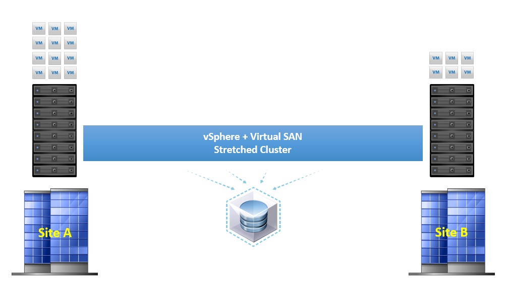
In the above scenario, we have virtual machines running on both sites so this is considered an Active/Active configuration, the Virtual SAN datastore is still a single datastore that covers both the sites as each site contributes storage to the VSAN datastore by equal capacities so in essence you have 50% of the VSAN datastore capacity on each site.

There is one question that springs to mind straight away based on the functionality of Virtual SAN….What about the Witness?.? As we know already the function of the witness is to provide >50% voting mechanism, and this is still the same in the stretched cluster, the witness still exists but this time in the form of an appliance based ESXi host which can be hosted on a third site, or even in vCloud Air.

In order to use the stretched cluster, three fault domains are required, one for each site, and a third for the witness, the below image shows this:

Stretched Cluster Witness

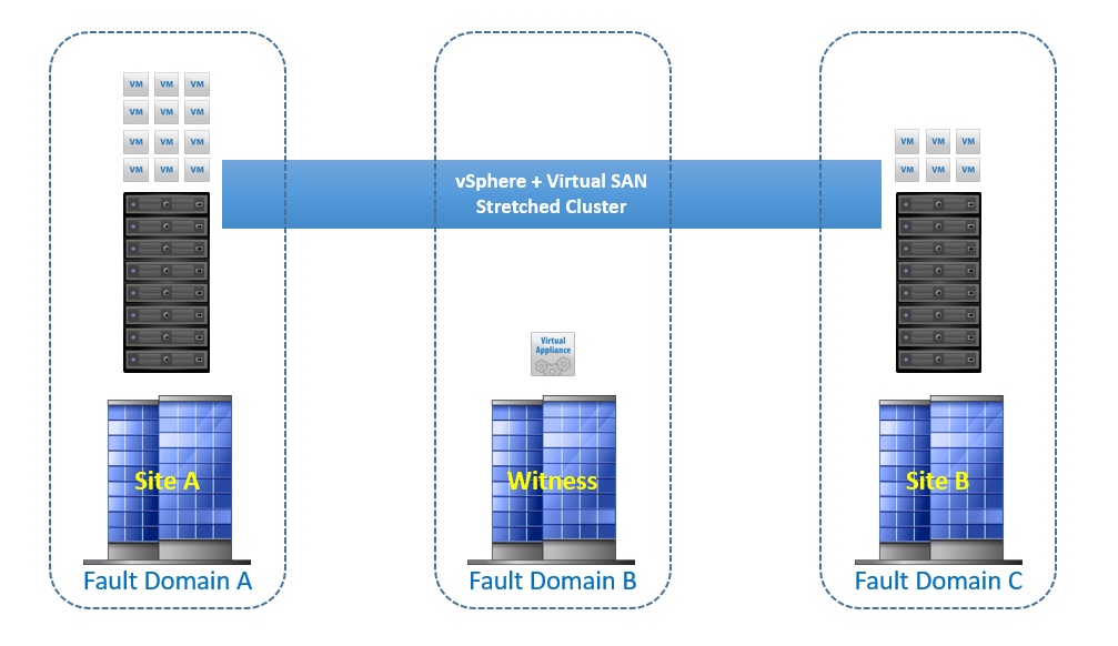
The witness only contains metadata, there is no I/O traffic from the virtual machines or VMDK data on the witness appliance, there are some space requirements for the Witness appliance though, each disk object residing on Virtual SAN needs 16Mb of storage on the witness, for example if you have 1000VMs and each VM has 4 disk objects, then the space requirement would be 4000 * 16 = 64Gb.? Each VMDK on the appliance is limited to 21000 Objects with a maximum of 45000 objects per stretched cluster.? The VMDKs for the appliance can be thin provisioned if needed in order to save space.


Another question that would be asked is what are the network requirements for the stretched cluster, the below image shows this:

Stretched Cluster Network

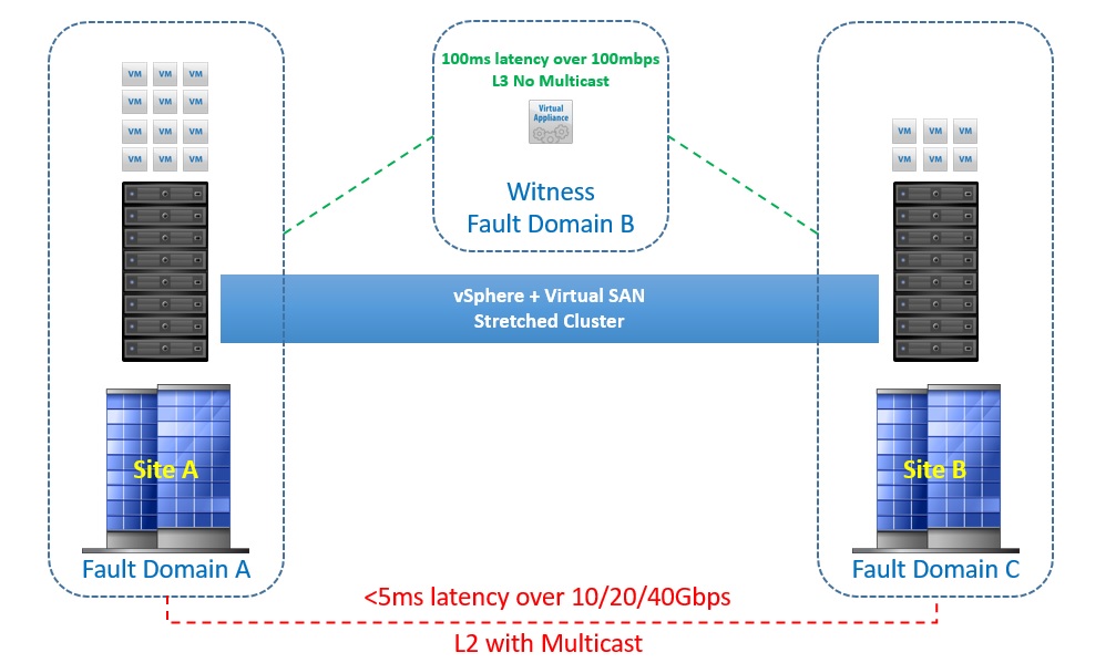
As you can see from the above image, the connection between the two sites must be at least a 10Gbps connection with latency no higher than 5ms, remember when a virtual machine submits a write, then the acknowledgement only comes when both sites have received the data with the exception of one site being down.

In addition to this, the link between the two data sites can also be routed over L3

The connection between each site and the witness site whether this be an on-premise third location or vCloud AIR needs to be at minimum a 100Mbit connection with a response time of no more than 100ms, there will be some relaxation on the response time based on the number of ESXi hosts and this would be as follows:

  • Up to 10 hosts per site, latency must be below 200ms to the witness
  • Above 10 hosts per site, latency must be below 100ms to the witness

The requirement of an L3 network between the main sites and the witness location, this is very important, putting them all on the same L2 network can result in I/O traffic going over the witness link which is not something you want to do

Other things to know:

Read Locality – With Virtual SAN data locality is not important, however with the stretched cluster read locality is important as it would be silly to have a virtual machine running on Site A and it fetching the reads from Site B, built into the stretched cluster functionality is the concept of read locality, the read requests will only come from the site/domain where the virtual machine compute is running, the writes will go to both sites.? If a virtual machine is vMotioned to a host in the other site, then the read locality will also switch to the site where the virtual machine compute now resides

Failures to Tolerate (FTT) – Since there are only two sites, then you can only configure storage policies with a maximum FTT=1, remember the formula for the number of fault domains required is 2n+1 where “n” is the number of FTT

Hybrid or All-Flash Both Hybrid and All-Flash will be supported with the stretched cluster functionality

Licensing – The stretched cluster functionality will only be included in the Virtual SAN Advanced licence, this license will also cover All-Flash, so any customer who already has a license for All-Flash is automatically entitled to use the Stretched Cluster functionality

What’s new in Virtual SAN 6.1

Since Virtual SAN was released in March 2014 we have seen various functionality and features added, below is a list of the major features added in the 2nd release of Virtual SAN (Version 6.0)

  • Fault Domain Support
  • Pro-Active Rebalance
  • All-Flash
  • Virtual SAN Health UI
  • Disk Servicability Functions
  • Disk and Disk Group Evacuation
  • JBOD Support
  • UI Improvements such as:
    • Storage Consumption Models
    • Resync Dashboard

Recently announced at VMworld Version 6.1 is no exception, with even more enterprise features being included, just to be clear Virtual SAN 6.1 is being released as part of vSphere 6.0 Update 1, so if you missed the announcement, here is a recap of the features:

  • Stretched / Metro Cluster with RPO=0 for sites no more than 100km apart and a response time of <5ms
  • 5 Minute RPO for vSphere Replication, this is exclusive to Virtual SAN
  • Multiple CPU Fault Tolerance (SMP-FT)
  • Support for Oracle RAC
  • Support for Microsoft Failover Clustering (DAG and AAG)
  • Remote Office – Branch Office (ROBO) 2 Node Virtual SAN Solution
  • Support for new Flash Hardware
    • Intel NVMe
    • Diablo ULLtraDIMM
  • Further UI Enhancements such as:
    • Integrated Health Check Plugin for Hardware Monitoring and Compliance
    • Disk and Disk Group Claiming enhancements
    • Virtual SAN On-Disk format upgrade
    • vRealize Operations (vROPS) integration

This clearly demonstrates the investment that VMware is making in Virtual SAN, I will be writing up on some of the features in more detail, particularly the Stretched Cluster and ROBO solution, so watch out for those


Disk failure testing on LSI Based Virtual SAN RAID0 controllers

Disk failure testing can be an integral part of a Proof of Concept, you want to ensure that Virtual SAN behaves in the correct way right?? In this post I shall talk about how to successfully perform disk failure testing on LSI Based RAID0 controllers in order to help you validate the behaviour expected from Virtual SAN.? Before I do that, I have seen many instances where people are attempting to simulate a disk failure by pulling a disk out of the backplane slot and not seeing what they expect to be expected behaviour, pulling a disk is not the same as an actual disk failure, Virtual SAN will mark a pulled disk as absent and will wait for the value of ClomRepairDelay (which the default is 60 minutes) before starting a rebuild of components residing on that disk.? With a failed disk Virtual SAN will rebuild components residing on that disk immediately, so you can now see the expected behaviour in the two different scenarios.

So how do we perform disk failure testing on an LSI Based RAID 0 controller?? Let’s first of all look at the different options we have


Health UI Plugin

In Virtual SAN? 6.0 there is the option to deploy the Health UI Plugin, this plugin for vCenter has a secondary routine that will deploy out components onto the ESXi host to allow them to report back to the the plugin on any issues that are seen, another part of this is the Error Injection routine that allows the user to inject a temporary or permanent device failure and also clear the injected error, for details on how to use the error injection, please refer to my post on Using the Error Injection Tool in the Virtual SAN 6.0 Health UI plugin to simulate a disk failure, for VSAN 5.5 users this feature is not available.


LSI based ESXi command line tools

LSI have a utility that is deployable on an ESXi host th manipulate and make changes to their controllers without having to go into the controller BIOS, the utility is very powerful and allows you to perform functions such as:

  • Create or Destroy a RAID Virtual Disk
  • Change cache policies
  • Change the status of Virtual Disks
  • Block access to Virtual Disks
  • Import Foreign Config

Please note: For the latest version of StorCli please visit the LSI Website for MegaCli please visit your server vendor website

Above are just a few examples of things that you can do using the command line tools.? Depending on who the OEM is for your LSI Based card, you would either use StorCLI or MegaCLI, we will cover both command sets for performing the same operation, for the cross references, I used this document from LSI, So which command option do we use to simulate a disk failure?

The obvious choice would be to set a RAID virtual disk or a Physical disk into an Offline state, before I seen the behaviour of doing this first hand I would have agreed 100%, however after seeing what happened after doing this made me look further at other options of achieving the same thing, but the question you may be asking is why would this not work?

When placing a RAID disk or Physical disk into an Offline state, what I observed in the ESXi logs is that there was no SCSI sense codes being received by the host from the controller, I could see a Host Side NMP Error of H:0x1 which equates to a No-Connect and the action from that is to failover, the disk was marked as Absent in the Virtual SAN UI but not failed, so obviously this is not what we wanted to achieve.? After a bit more digging and testing I finally stumbled across an option which after testing a few times resulted in the correct behaviour, so what was the option?

> storcli /c0 /v2 set accesspolicy=blocked

In the above command I am selecting Controller 0 with the /c0 option, and Virtual Disk 2 with the /v2 option, what this did is block access to the RAID Virtual Disk and send SCSI Sense Code information to the ESXi host which was:

  • Device Side NMP Error D:0x2 = Check Condition
  • SCSI Sense Code 0x5 = Illegal Request
  • ASC 0x24 = Invalid Field in CDB
  • ASC 0x25 = Logical Unit not Supported

This resulted in the disk being reported as Failed which was the expected behaviour, the desired command for MegaCli is as follows:

> MegaCli -LDSetProp -Blocked -L2 -a0

Where -a0 is the adapter number and -L2 is the Logical Drive number (Virtual Disk)

After the disk failure testing has been completed, in order to remove the blocked access to the Virtual Disk you issue the following StorCli command:

> storcli /c0 /v2 set accesspolicy=RW

And in MegaCli

> MegaCli -LDSetProp -RW -L2 -a0

After you have re-allowed access to the Virtual disk you will need to go into the Virtual SAN UI and remove the affected disk from the disk group and re-add it back in, the same applies if you was performing the failure test on the SSD that heads a disk group, only this time you will have to remove the whole disk group and re-add, after all you have just in effect replaced a failed disk 🙂